Picture of the Day – November 12th
SONY DSC


SONY DSC
ASTRONAUT TOOLS
Jon Clarke
Astronauts have used a wide range of tools over the years to perform their tasks. Some, some as the geological hammers used by the Apollo astronauts on the Moon, were almost identical to what would be used on Earth. Other tools, like the “flyswatter” used to deal with an errant satellite by the crew of STS-51D, are more specialised.
The Apollo astronauts on the Moon also used many other tools – tongs, scoops, and rakes to pick up different types of surface sample; various cameras; small shovels; rotary drills; scribers; push corers, and a curious device called gnomon to orient photographs. Future astronauts on Mars will probably use similar tools, as well as new instruments that have been developed in the interim – multispectral cameras, continuous individual video, hand held spectrometers, XRF and XRF analysers, as well as tools designed to deal with the need for contamination-free samples for astrobiology research.

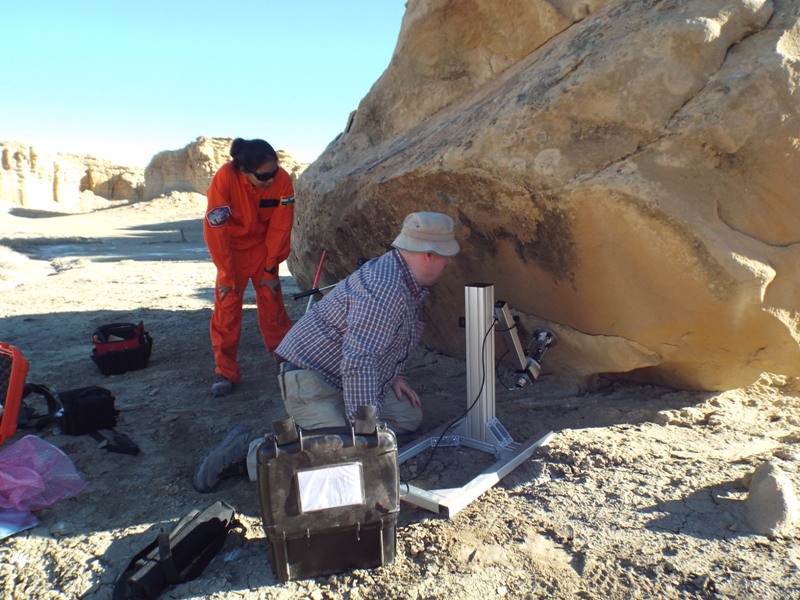
Dr Mike-Curtis-Rouse of the UK Space Agency (right) and myself testing SPLIT near MDRS
Earlier in I had the privilege to test one such tool, the SPLIT, a small percussive tool developed by the UK Space Agency to expose contamination-free fresh rock surface by robots or astronauts. With Dr Mike Curtis-Rouse of UKSA I trialled this tool on a number of different rocks in the vicinity of MDRS.
SPLIT being set up in platform mode near Factory Butte by John Holt of Leicester University, Anushree looks on.
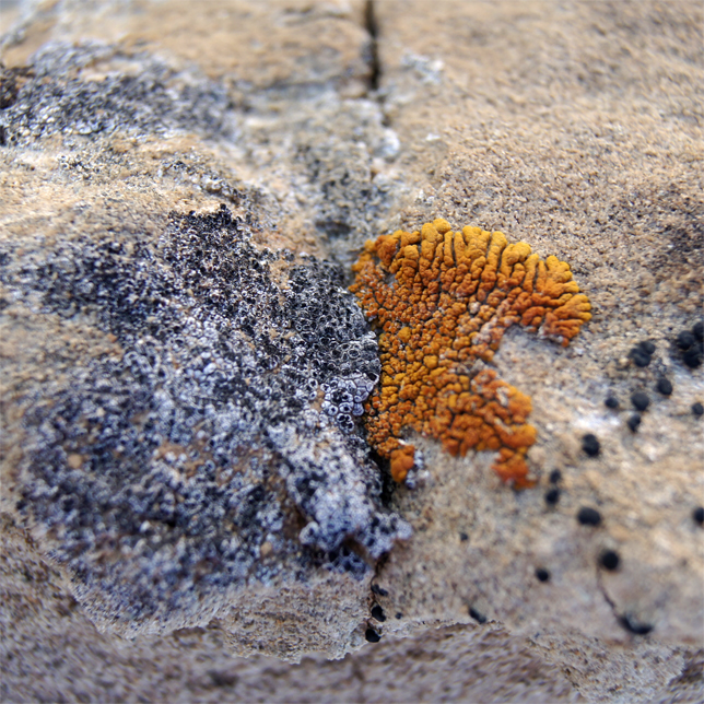
The next day we tested the SPLIT in platform mode, as if it were on a robotic rover near Factory Butte. SPLIT pecked away at fractured rock surfaces until they fell away, exposing fresh rock that could be scanned by rover instruments. The chosen tests sites were all accessible by a robotic rover. They were overhanging and north-facing rocks with one or more metres of overlying material. Such locations on Mars would offer substantial radiation protection for organics or extent life. SPLIT successfully exposed organics beneath a gypsum vein on one of the trials.

Green microorganisms living beneath gypsum vein exposed by SPLIT
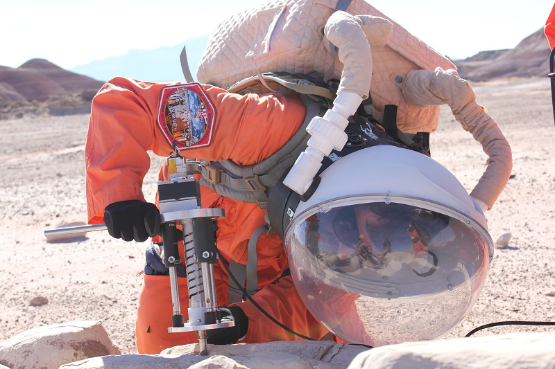
Mark Edward, also of the UK Space Agency donned a MDRS suit and scanned a range of in the Factory Butte area with a portable laser Raman spectrometer to determine mineralogy and organic content. Improved versions of this tool is likely to be among the suite available to astronauts on Mars because of its simplicity, capability, and portability. Incidentally, November 7th was the anniversary of the birth of C. V. Raman, the Indian physicist who discovered the Mossbauer Effect for which he was awarded the Nobel Prize in 1930. I wonder what he would have thought of instruments based on his discovery one day flying to Mars?

Mark Edwards of the UK space Agency successfully testing a field portable laser Raman spectrometer while wearing a MDRS suit.
Evaluation proceeds both ways. So the UK Space Agency people who wore our suits gave us useful feedback about temperature, ventilation, and the need for water supply to the wearers of the MDRS suits. No doubt these suggestions will be included in future versions.
Sol Summary Report (SSR):
Sol# 50
Person filling out report: Annalea Beattie
Summary Title: Where do the days go ?
Mission Status: On track
Sol Activity Summary:
Lots of media outreach and catching up with paper work today. In the morning we did health and wellbeing interviews with our HSO. Anastasiya interviewed Yusuke for her journalist report and I interviewed Anushree for my space.com blog on CapCom.
(Anu is a CapCom team member as well as a member of our crew).
After lunch we heard voices (almost an anomaly) and looked out the window to see Shannon busily engaged outside with visitors – what looked like several large families with lots of kids. Apparently they all peered in through the laboratory window where Jon was processing geology samples and Shannon told the kids he was of Martian birth. Which he might be. Jon today also wrote a report on the tectonic hammer SPLIT.
With the assistance of Yusuke, Claude-Michel spent all day working on the smartpot project, replanting and topping up Ph and nutrients.
Anu continued her sample processing and Alex worked on his project and wrote a technology post, (and gym of course). I’ve cooked a chicken curry in slow pot overnight. Yoga, a highlight as always.
MDRS lessons:
Plans: Sunday, a day of rest.
Crew Physical Status: Great. All of us are fine.
Weather: Cool start this morning, beautiful day, clouding over, now dark.
Anomalies: Nothing. Regular as clockwork in so many ways.
I am still debugging stuff here and there. While I am waiting better time to be able to share more about the capability of the SSUIt prototype, this post will go deeper into the technical details.
Fasten your seat belt, let’s go!
As I said, or as I should have said already, the purpose is to make our EVA more realistic in term of technology interaction while on the field. I thought that a small computer, some sensors and a screen would do the trick.
My choice for the computer, the Raspberry Pi, was arbitrary. Still the community is wide spread around the world and I knew that if I was stuck somewhere, I would be able to find a lot of resources to help me moving forward. But nowadays, there is a lot more small computers. And maybe another one would have been better than the Raspberry Pi v3 I am currently using.
Let’s review some of the RPi features.
The board has standard USB ports. It is good to plug mouse, keyboard, flashdrive etc. While, I never expected to use a mouse or a keyboard on the field, it is still handy for debugging back into the Hab.
It has a Display and Camera Serial Interface ports (DSI and CSI). The DSI was never meant to be used. But the CSI could have been used for a 5Mpx camera. That would have add a nice feature for in situ reporting with pictures.
It has HDMI port. We can plug in HD screens but also smaller ones like the one intended to carry on the arm.
It has General Purpose Input/Output (GPIO) that come as a 40 pins header. Some of the pins are dedicated to special buses:
These buses are very helpful to communicate with external devices, such as the sensors.
One drawback of the RPi is that it does not come with Analog Digital Converters (ADC). And there is not built-in several UART serial buses. That would have saved me the pain of adding another layer into my project…
Most of my sensors are communicating through the I2C bus. This bus is a half-duplex synchronous protocol for communication. The master (here is the RPi) is issuing a clock signal (1st wire) on which all the bits send or received must be synchronized (2nd wire). Many devices can be connected to this bus. Each sensor has a different 7-bits address so that when the master calls one, the others stay quiet. Most of the sensor have a factory set address, and cannot be changed. When you have two sensors with the same address (likely to happen if you need 2 or more same sensors on different places), as I did, you must find a way around. Which, in my case consisted in muting the clock wire that goes to the first sensor when I want to communicate with the second one and vice versa.
The GPS chip I found communicate through the UART serial bus. This bus is a full-duplex asynchronous protocol for communication. It is suited to connect 2 devices (only) with 2 wires. The first wire is used to send data from the 1st device to the 2nd one. The second wire is used to send data from the 2nd device to the 1st one. There is no master/slave relationship on this protocol, so that each device can communicate to the other one at any time. The drawback is that you cannot connect more than one device per bus. In my case I could have used one more since my radio ship communicate through the same bus. So I needed to find a way to add one UART bus.
And then I have the heartbeat sensor that is a one wire analogue signal. Without an ADC, it is not possible to exploit numerically the signal. Also the battery voltage is a good indicator to have while on EVA. That also requires an ADC converter (in addition of a voltage divider).
As I was learning programmable electronic for this project, I have also been in touch with the Arduino world. The Arduino Nano board comes with the same buses as the Raspberry Pi plus some pins for ADCs. So the ADC pins I was seeking for and the additional UART serial bus are available on this 1$ micro board. I just needed a way to communicate with it from the RPi.
The I2C bus will not be fast enough to transfer all the data, without taking into account that the RPI I2C bus is already very busy with the other sensors. Furthermore, programming the Arduino to be an I2C slave device (while it is commonly used as a master) is just a pain.
There is a USB port that is usually used for programming the board but can be used also as a serial interface for transferring data.
Instead I choose to go for the SPI bus which is full-duplex synchronous protocol. The master issue a clock signal (1st wire) on which all the bits send or received must be synchronized (2nd and 3rd wires). Since it is a full-duplex communication one wire serves to receive data from the slave by the master (called MISO: Master In, Slave Out) while the other wire serves to send data from the master to the slave (called MOSI: Master Out, Slave In). The other wires, 4th and so on, are used to control several peripherals on the same bus as an On/Off switch. Since the bus is totally controlled by the master (the RPI) the slave cannot send data whenever it wants. So any data that is collected by the slave (the Arduino Nano) must be stored into a buffer while waiting for the master to call in and authorize communication. Another difficulty is that the Arduino is not multitasking. It is either ADCing the signal or sending the data out. It needs to be sure that sampling the ADC pin will not have to occur during sending the data out.
Below find the schematic of the hardware architecture. The SPI line between the Arduino Nano and the Raspberry Pi is stroke because currently, the software is not ready for reading data on this bus (everything is wired though). Each part belong to the SSUIt prototype except for the battery that belongs to the backpack.

Next time I will present the software architecture.
Stay tuned!
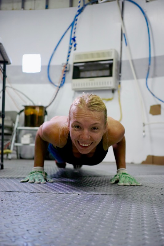
Anastasiya training

`

Engineers discussion


Setting up new lab
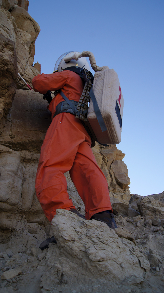
Working with geology tool